- Order number: 24-2581-2656
- Graduation: 1
- Minimum Quantity: 1
- Maximum Quantity: 500
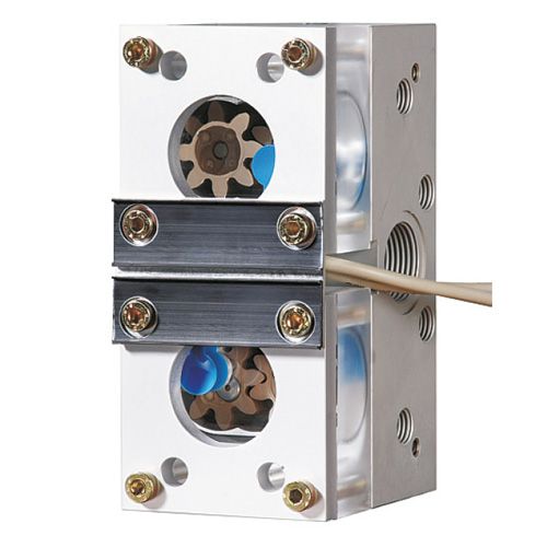
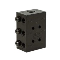
- Flow restrictor SMD 2 for SKF CircOil oil circulation lubrication systems
- Nominal volume flow per flow restrictor: 0.1 - 8 l/min
- Pressure: max. 16 bar
- Operating viscosity: 50 - 650 mm²/s
- Operating temperature: 0 to 70 °C
- CE conformity mark
Flow restrictors SMD 1B / SMD 2 / SMD 3 in modular design with gear flow control and bypass system for oil circulation lubrication systems
The purpose of the flow restrictors is to divide the volume flow of the main line into parallel individual volume flows as required and to shut off individual lines if necessary. Flow restrictors have proven to be reliable and flexible, particularly in paper machines, which often have several hundred lubrication points. Throttle systems are also used where minor adjustments and corrections in the lubricant supply should be able to be carried out while the machine is running. To make it easier to service and reduce downtime, a bypass function has been integrated into the flow restrictors as standard. This makes it possible to carry out any service work on the wheel chamber/sight glass without adjusting the throttle setting (throttle spindle) and without affecting the lubricant supply.
Advantages
- Modular design, which means that the lubrication system can be adapted to machines and systems at any time.
- Volume flow adjustment by adjusting the throttle spindle. The oil volume flow can be continuously adjusted even when the machine or system is running.
- The setting ranges of the flow restrictor are:
SMD 1B at 0.05 to 1.0 l/min.
SMD 2 when using a fine throttle spindle at 0.1 to 4.4 l/min, with a coarse throttle spindle at 4 to 8.0 l/min.
SMD 3 at 4 to 40 l/min. - With electrical gear monitoring (inductive sensor according to NAMUR). The combination of optical and electrical control provides the best possible volumetric monitoring of the volume flow.
- User-friendliness thanks to the bypass system. Any service work that may be required can be carried out without adjusting the throttle spindle and without interrupting the lubricant supply.
- Service-friendliness thanks to the option of a flushing connection upstream of the restrictor.
Application
SMD series flow restrictors are mainly used in oil circulation lubrication systems in paper machines. They have particularly distinguished themselves through their reliability, maintenance-free operation and flexibility.
How the flow restrictor works
The lubricant coming from the supply line flows from the inlet of the flow restrictor housing into the wheel chamber of the gear flow control and via the gears to the throttle spindle. The flow rate is regulated by selecting (fine, fine or coarse throttle) and adjusting the throttle spindle. After passing through the throttle spindle, the metered volume flow of the lubricant flows to the outlet of the flow restrictor housing.
How the gear flow control works
The lubricant coming from the supply line flows from the inlet of the flow restrictor housing into the wheel chamber of the gear flow control and via the two gears to the throttle spindle. The volume flow generated in this way causes the gears in the wheel chamber to rotate. A NAMUR sensor mounted above one of the gears records the revolutions (pulse reduction) of the gears and thus the flow rate. The number of pulses (flow rate) recorded by the NAMUR sensor depends on the gear speed
Bypass closed (operating position)
The lubricating medium flows from the inlet via the gear flow control wheel chamber and via the throttle spindle of the throttle to the outlet.
Bypass opened (service position)
If the bypass is opened by turning the fitted bypass spindle, flow through the wheel chamber is prevented and the lubricating oil flows directly from the inlet via the throttle point to the lubrication point.


